Privacy statement: Your privacy is very important to Us. Our company promises not to disclose your personal information to any external company with out your explicit permission.

It is unfortunate that many leaks identified in hydraulic systems are left to drip away the profits of a company. And it is not just the cost of the hydraulic oil itself-profits are also lost to unnecessary energy consumption, reduced equipment performance, decreased reliability, increased housekeeping costs, increased maintenance costs, damage to hydraulic systems and components and many more costs.
Leaks often go unnoticed because there are no visual indications to alert operators or technicians of the problem until system performance has been severely affected. The components with these leaks are typically repaired in an unplanned, fire-fighting mode of breakdown maintenance. If the problem had been caught earlier, it likely could have been fixed during planned downtime, resulting in lower associated costs and less impact on productivity.
Identifying and controlling hydraulic system leakage is something that every company with hydraulic assets should be interested in. Hydraulic systems can leak both internally and externally, causing different issues and requiring different solutions.
These problems can be tackled in a variety of ways from making simple lubricant changes to integrating advanced tools that help your teams detect and manage hydraulic leaks. But the key to any approach is faster, earlier detection and fast response. Let`s look at a few ways to accomplish this.
There are many ways to help yourself and maintenance and operator teams to identify problem leaks more quickly, saving time, money, and headaches. The faster a leak is identified and reported, the more time you have to respond before it causes problems like loss of performance or long-term damage to your hydraulic equipment.
Consider using a hydraulic oil that has a distinctive color vs your other lubricants and fluids. This can help both skilled and entry-level staff to identify when a leak is hydraulic in nature and prioritize reporting the problem quickly and appropriately.
Can your operators, technicians, and maintenance staff all quickly identify a hydraulic leak vs another fluid leak in your equipment? If not, you`re likely not catching important hydraulic leaks as quickly as you could. If the hydraulic oil is a different color, it`s easy to instruct staff to immediately report [green fluid leaks" (or whatever color your hydraulic fluid may be) to the proper person as soon as they are spotted.
These simple steps are a great place to start improving your hydraulic leak detection and management with very little associated cost or effort, but they can be supplemented with other approaches as well. Taking an in-depth look at record keeping and surveillance based on monitoring leakage within hydraulic systems is a good way to understand trends over time By matching this data with a robust plan for performing repairs and/or modifications aimed at the root causes of the leaks, significant progress can be made.
Not all leaks hydraulic leaks are very visible, or even necessarily bad. The vast majority of hydraulic systems in operation today have leaks-leaks that are planned. They are designed with a specific function in mind and. in many cases, are documented by the original equipment manufacturer (OEM) as the amount of acceptable leakage under normal operating conditions.
Such internal planned leakage typically occurs through small orifices or pathways that allow a fluid from a higher pressurized zone of a system to travel into a lower pressurized zone to lubricate, clean and cool a specific component or area. These planned internal leaks do not allow the fluid to exit the hydraulic circuit, so there is no visual indication of its presence. The most common cause of unplanned, excessive internal leakage is wear of component surfaces during normal operation. Leakage can also result from poor system design, incorrect component selection, poor quality control tolerances during the manufacturing of a component or incorrect overhaul of rebuilt components.
The first symptoms of excessive internal hydraulic leakage are decreased system performance or reliability and increased operating temperatures,
The major power loss hydraulic systems usually experience is the result of internal leakage on pumps and motors. This leakage is the result of excessive clearances within the pumping mechanisms of the pumps and motors resulting in reduced volumetric efficiency. Slippage-a common term used to describe the volumetric loss of a pump/motor-is typically identified when the input energy remains the same or higher, but less work is being performed in the hydraulic circuit.
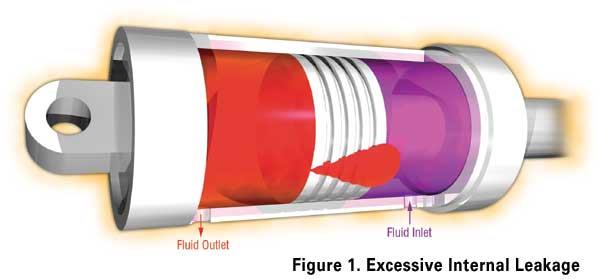
In hydraulic cylinders, cylinder rod drift or creep and the cylinder`s inability to hold the designed load would be identified by increased leakage. The excessive leakage is the result of the fluid bypassing a piston seal either through a worn seal or a worn cylinder barrel (Figure 1).
In spool valves, excessive internal clearances between the spool and the valve body decrease control and stability of the hydraulic circuits and their functions. Profit-robbing energy loss is the result of energized fluid that is allowed to escape back to the reservoir through a spool valve that has an out-of-specification clearance problem.
Relief valves or other spring offset valves with a weak spring or a jammed open condition will have the same effect of fluid energy loss by allowing the pressurized fluid to bypass the working circuit.
Low fluid viscosity or excessive heat (reducing the effective viscosity of a fluid) will also increase leakage rates. This form of internal leakage reduces system performance and decreases fluid film strength, which will also result in premature wear of the equipment surfaces and the fluid`s properties.Eventually, all of these conditions will affect hydraulic system performance, and ultimately company profits. Detection of unplanned internal leakage in most cases would rely on specific tools to examine the location and quantity of the leak.
Performance issues or the inability of a circuit to perform its designed function typically triggers craftsmen to install flow meters in various locations (such as case drains on pumps) to detect excessive leakage resulting from unacceptable clearances in mating surfaces.
Many companies install flow meters on the case drains of pumps and motors to determine when to overhaul these components before performance is severely affected. In critical automated positioning systems, both the control valves and the hydraulic cylinders could require periodic bench testing to ensure an acceptable leakage rate is maintained. At this point, all components that fall outside the acceptable standards would require an overhaul ensuring that OEM minimum standards are achieved.
OEMs recommend an optimum operating viscosity required by their equipment to perform within the design parameters. In many cases, selecting a fluid and maintaining an operating temperature which achieves the OEM recommended viscosity become the responsibility of the end user.
Temperature measurement at the critical components ensures equipment is operating within that optimum range. Use of the Viscosity-Temperature Standard Charts (ASTM D341) assists in determining these variables (Figure 2).
Noncontact infrared thermometers are useful for nonobtrusive measurement of operating temperatures of equipment. An abnormal temperature increase at a relief valve could indicate that the valve is in a bypassing condition. This bypass condition will generate heat locally in the component; in many cases, the anomaly would have gone undetected by monitoring the system reservoir temperature because of system coolers or dissipation of heat throughout the system.
Ultrasonic detection has proven to be another effective method of determining high pressure or high velocity leaks in various locations of valve and cylinder leakage. This method enables the localization of the internal leakage; but similar to temperature reading, the results are not quantifiable into the amount of leakage. The only quantifiable method is to measure the flow or quantity of fluid loss in a given time frame using a flow meter or other related test equipment.
|
External leakage is the most recognizable type of leakage. Even the untrained eye can easily spot a broken hose spewing oil like a Texas geyser. These types of leaks will typically be repaired quickly, because the equipment, production line or process will quickly come to a halt if the problem is ignored.
The constant drip or drop is not always repaired because system performance and production are usually not affected. The location and/or quantity of the leaked fluid is in many cases like [Waldo" - hard to find - and the repair not really worth the effort (Figure 4).
Many companies spend tens of thousands of dollars a year replacing top-up fluids, not really understanding the financial impact of a drip. Reports show that the replacement cost of a fluid can cost five times more than the cost of the new fluid. Two areas that are not represented in the fluid replacement costs and should be to renew the interest in repairing leaks are:
1. Safety Issues
2. Environmental Issues
Both of these areas have personal and financial implications when leaks are allowed to exist without competent maintenance practices to eliminate them.
Detection and quantification of the fluid consumption is the first step in external leak control. Up-to-date reservoir management records must be maintained to determine when, by whom and how much fluid was required to top-up a reservoir. These records should be used along with visual inspections to determine the location and the leak rate of any detected anomalies.
SAE J1176 Leak Classification Tables is a method used to quantify leaks once they have been located (Figure 5). Quantification of the leakage rate and location will allow for the opportunity to prioritize the repairs. In many cases, the source and quantity of the leaks cannot be determined, as they are difficult to see. The best practice recommends occasionally cleaning an area and fully wiping down equipment to examine the leaks.
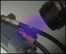
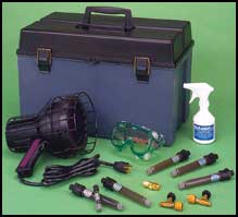
When leaks are too small or too numerous to see clearly, you can take the color dye a step further by adding dyes sensitive to black light.. This liquid dye is formulated to be compatible with the existing hydraulic fluid and machine surfaces.
The dye is mixed into the reservoir after which the mixture will emit a bright green/yellow glow when struck by the rays of a black light (Figure 6). This method of visual detection helps determine whether the fluid being viewed is from an active leak from the system in question (Figure 7).
 |  |
| Figure 6. Fluorescent Dye Leak Detection | Figure 7. Visual Enhancement Dyes |
The changing workplace, the environment and the need for equipment reliability require a concerted effort to monitor and maintain all unplanned leaks. While you can take simple steps now that may offersignificant savings, many companies have found success by creating entire Any leakage control programs that begin with the original equipment design and are maintained throughout the lifecycle of the equipment. This sort of investment helps to preserve system viability and system integrity long term.
With the right training, lubricants, and equipment in place, you will be able to quantify, characterize, analyze all types of leaks. This collected information can give maintenance professionals an opportunity to perform leakage control activities by planning ahead and being proactive about their maintenance and reliability goals., If you are able to properly manage hydraulic system leakage, you will be able to achieve reduced energy consumption, reduced waste, increased uptime, improved equipment reliability and ultimately increased company profits.
July 25, 2022
The service life of various hydraulic valves in the hydraulic support is very low. The way and solution for solving the problem abroad is to improve the filtration precision of the system and improve...
In this paper, we will analyze the last cause of the failure of the hydraulic valve in the future: cavitation. In this paper, we will analyze the last cause of the failure of the hydraulic valve in...
BWCB insulation gear pump motor high temperature reasons and countermeasures analysis 1, cause analysis (1) motor power, large operating current, large heat. (2) The fan speed is low, the wind...
Gear oil pumps are mainly used in the transfer, oil pressurization, fuel injection, etc. of oil media in chemical, petroleum, mining, metallurgy, power station and other industries, as well as in the...
Email to this supplier
July 25, 2022

Privacy statement: Your privacy is very important to Us. Our company promises not to disclose your personal information to any external company with out your explicit permission.

Fill in more information so that we can get in touch with you faster
Privacy statement: Your privacy is very important to Us. Our company promises not to disclose your personal information to any external company with out your explicit permission.